Introduction
Heating, ventilation, and air conditioning (HVAC) system is designed to achieve the
environmental requirements of the comfort of occupants and a process. HVAC systems are more used in
different types of buildings such as industrial, commercial, residential and institutional buildings.
The main mission of HVAC system is to satisfy the thermal comfort of occupants by adjusting and changing
the outdoor air conditions to the desired conditions of occupied buildings. Depending on outdoor
conditions, the outdoor air is drawn into the buildings and heated or cooled before it is distributed
into the occupied spaces, then it is exhausted to the ambient air or reused in the system. The selection
of HVAC systems in a given building will depend on the climate, the age of the building, the individual
preferences of the owner of the building and a designer of a project, the project budget, the
architectural design of the buildings.
HVAC systems can be classified according to necessary processes and distribution process. The required
processes include the heating process, the cooling process, and ventilation process. Other processes can
be added such as humidification and dehumidification process. These processes can be achieved by using
suitable HVAC equipment such as heating systems, air-conditioning systems, ventilation fans, and
dehumidifiers. The HVAC systems need the distribution system to deliver the required amount of air with
the desired environmental condition. The distribution system mainly varies according to the refrigerant
type and the delivering method such as air handling equipment, fan coils, air ducts, and water pipes.
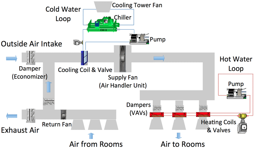
Fig 1: Construction Of AHU Unit
How do a Chiller Work?
A chiller works on the principle of vapor compression or vapor absorption. Chillers provide
a continuous flow of coolant to the cold side of a process water system at a desired temperature of
about 50°F (10°C). The coolant is then pumped through the process, extracting heat out of one area of a
facility (e.g., machinery, process equipment, etc.) as it flows back to the return side of the process
water system.
A chiller uses a vapor compression mechanical refrigeration system that connects to the process water
system through a device called an evaporator. Refrigerant circulates through an evaporator, compressor,
condenser and expansion device of a chiller. A thermodynamic process occurs in each of above components
of a chiller. The evaporator functions as a heat exchanger such that heat captured by the process
coolant flow transfers to the refrigerant. As the heat-transfer takes place, the refrigerant evaporates,
changing from a low-pressure liquid into vapor, while the temperature of the process coolant reduces.
The refrigerant then flows to a compressor, which performs multiple functions. First, it removes
refrigerant from the evaporator and ensures that the pressure in the evaporator remains low enough to
absorb heat at the correct rate. Second, it raises the pressure in outgoing refrigerant vapor to ensure
that its temperature remains high enough to release heat when it reaches the condenser. The refrigerant
returns to a liquid state at the condenser. The latent heat given up as the refrigerant changes from
vapor to liquid is carried away from the environment by a cooling medium (air or water).
Types of Chillers
Water Cooled Chiller
Water-cooled chillers feature a water-cooled condenser connected with a cooling tower. They have
commonly been used for medium and large installations that have a sufficient water supply. Water-cooled
chillers can produce more constant performance for commercial and industrial air conditioning because of
the relative independence to fluctuations of the ambient temperature. Water-cooled chillers range in
size from small 20-ton capacity models to several thousand-ton models that cool the world’s largest
facilities such as airports, shopping malls and other facilities.
A typical water-cooled chiller uses recirculating condenser water from a cooling tower to condense the
refrigerant. A water-cooled chiller contains a refrigerant dependent on the entering condenser water
temperature (and flow rate), which functions in relation to the ambient wet-bulb temperature. Since the
wet-bulb temperature is always lower than the dry-bulb temperature, the refrigerant condensing
temperature (and pressure) in a water-cooled chiller can often operate significantly lower than an
air-cooled chiller. Thus, water-cooled chillers can operate more efficiently.
Water-cooled chillers typically reside indoors in an environment protected from the elements. Hence,
water-cooled chiller can offer a longer lifespan. Water-cooled chillers typically represent the only
option for larger installations. The additional cooling tower system will require additional
installation expense and maintenance as compared to air-cooled chillers.
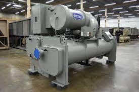
Fig 2: Water Cooled System
Air Cooled Chiller
Air-cooled chillers rely on a condenser cooled by the environment air. Thus, air-cooled chillers
may find common application in smaller or medium installations where space constraints may exist. An
air-cooled chiller can represent the most practical choice in scenarios where water represents a scarce
resource.
A typical air-cooled chiller can feature propeller fans or mechanical refrigeration cycles to draw
ambient air over a finned coil to condense the refrigerant. The condensation of the refrigerant vapor in
the air-cooled condenser enables the transfer of heat to the atmosphere.
Air-cooled chillers offer the significant advantage of lower installation costs. Simpler maintenance
also results due to their relative simplicity as compared to water-cooled chillers. Air-cooled chillers
will occupy less space, but will mostly reside outside a facility. Thus, the outdoor elements will
compromise their functional lifespan.
The all-inclusive nature of air-cooled chillers reduces maintenance costs. Their relative simplicity
coupled with reduced space requirements produces great advantages in many types of installations.
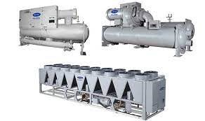
Fig 3: Air Cooled Chiller System
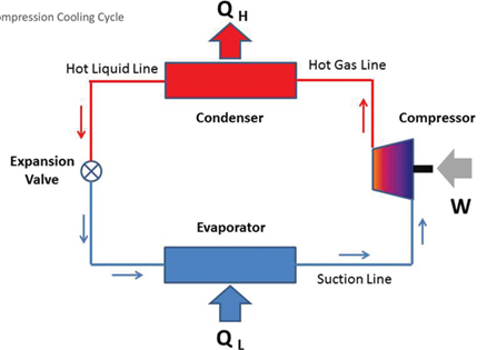
Fig 4: Vapor Compression Cycle
Instructions
- Specifications of the machine should be written down from the name plate or technical literature.
- Ensure that the thermo-wells are clean and filled with suitable fluid, a few hours before the test.
- Ensure that the chilling package is in operation for sufficient time to achieve steady state temperature and flow rate conditions, close to normal operating temperatures, before beginning measurements.
- It may be noted that testing of the chiller at partial refrigeration load is permitted but the load should be steady during the test.
- Access to the electrical power panel should be ensured to enable simultaneous measurement of electrical parameters along with the temperature differential across the chiller. It is advisable to keep the portable power analyzer connected through the duration of the test.
- In the case of fuel-fired machines, calibrated in-line flow meters or calibrated fuel day tanks should be available for fuel flow measurement.
- For steam turbine driven equipment, calibrated in-line steam flow meter should be available for steam flow measurement.
- For steam heated absorption chilling packages, calibrated in-line steam flow meter or arrangement for collecting steam condensate in a calibrated container should be available for steam flow measurement.
- For liquid flow measurements, use of in-line calibrated flow meters is recommended. In the absence of in-line meters, transit type ultrasonic flow meters may be used.
- It is desirable that performance characteristics of associated pumps are available for a quick check of estimated water flow rate, using ultrasonic flow meters for measurements.
Precautions:
- Request the machine operator to ensure that all necessary installed instruments and safety trips are operational.
- Use appropriate safety precautions while taking measurements on live cables with portable instruments.
- Make sure the clamp-on jaws of current transformers are completely closed.
- Some of the anti-freeze agents used for brine solutions may be corrosive and irritable for the skin, eyes etc. hence due care should be exercised.
- Maintain a safe distance from live electrical equipment and rotating mechanical equipment during measurements. Ensure that at least two persons are present at the time of measurements.
- Use safe access routes or safe ladders to access measurement points located at a height. (Unsafe practices like stepping on working or idle motors, compressors, belt guards, valves should be avoided).
- Be sure of the location of the “emergency stop” switch of the machine before start of any test.
- Tapping’s from pipe lines for pressure and flow measurements should be flushed before measurements as these may be choked due to liquid stagnation.
Instruments
- Transit Time Ultrasonic flow meter
- Vane Anemometer
- Hot wire anemometer
- Pitot tube
- thermo-wells
- Calibrated mercury in glass thermometer (bulb diameter not greater than 6.5 mm).
- Calibrated thermocouple with calibrated indicator.
- Calibrated electric resistance thermometer.
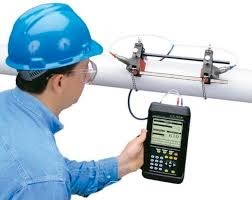
Ultrasonic flowmeter
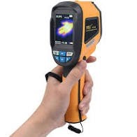
Infrared Thermometer
Thermocouple
Instructions for Layman
- Number of appliances in a room
- Wattage of each appliance
- Hours of use
- light should be kept on for 30mins before conducting the audit
- Fan should be at maximum speed
- Star rating of AC should be noticed